
Computational Modeling
Particle-in-Cell
Recently, I have been investigating the use of XOOPIC to model the self-bias effect. XOOPIC is a 2-D (space), 3-D (velocity) particle-in-cell code that was developed by John Verboncoeur's research group while at UC-Berkeley (he's now at Michigan State University). Particle-in-cell codes use "super-particles" to represent many physical particles (electrons and ions). These particles have the same mass and charge as the constituent physical particles they represent. They are moved around by the externally imposed and self-consistent fields that are generated by their movement and location. In order to avoid calculating the interaction of each particle with every other particle, the charge and current are calculated on a mesh of points and these values are used to calculate the resulting electric and magnetic fields. The particles are then moved in response to these fields. This process is repeated with short time steps (typically tens of nanoseconds) for many thousands of steps, and the system evolves until desired phenomena emerge. Particles can be created or removed during the stepping, subject to boundary conditions or ionization that can be modeled using a random process such as the Monte Carlo method.
Wave Codes
Our research group has developed two finite difference codes to calculate the electromagnetic fields generated by various RF antennas in a cylindrical plasma column.
ANTENAII
ANTENAII is a linear, 1-dimensional code that uses a variable-step integrator to calculate the 3-D wave fields in a cylindrical magnetized plasma with a radially varying density profile. Maxwellian velocity distributions and Landau damping are included and collisional effects are included using the Krook model. The antenna used in the experiment, the half-turn double helix (see below), has been added recently. The user specifies the antenna current and plasma properties, and the code calculates the field values at a series of user-specified locations in one dimension (r, z, kz, etc.).
MAXEB
MAXEB is very similar to ANTENAII but includes the ability to specify a axial magnetic field profile, and calculates the 3-D electromagnetic fields in two dimensions (r and z). The fields are Fourier-analyzed in the third dimension.
Experimental (UW-Madison)
Helicon sources are very efficient plasma sources that launch a special type of wave in a magnetized plasma column called a helicon wave. These sources typically operate at a few mTorr of background gas pressure (typically argon) with moderate magnetic fields (several hundred Gauss). The wave is launched by an RF antenna wrapped around the cylindrical chamber, supplied with up to a few kW of RF power. These sources can also operate in additional modes including capacitive and inductive coupling.
The helicon plasma facility was developed to investigate the physics and applications of these very efficient sources. These sources are capable of high plasma densities in the range of 1011 to 1014 cm-3 with relatively little input power. We have examined and continue to investigate helicon wave coupling, neutral depletion, double layer ion acceleration, and magnetic nozzle effects. Applications for helicons range from materials processing to high-efficiency ion sources to potential plasma thruster designs.

Facility

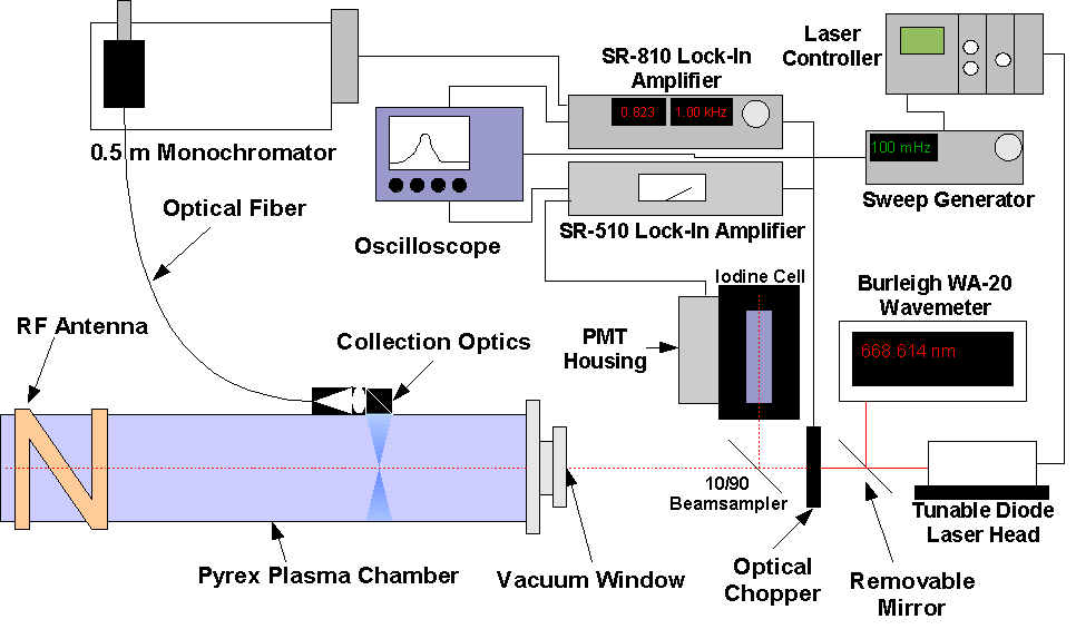
The Madison Helicon eXperiment consists of a Pyrex plasma chamber surrounded by a number of electromagnetic coils used to produce a DC magnetic field. The fill gas (typically argon) is fed into the upstream side of the chamber. The other end of the chamber has a stainless steel expansion chamber with a mechanical and turbo pump attached for maintaining the vacuum (~ 10-6 Torr base pressure). The plasma is created with 13.56 MHz RF power that can be delivered as 6 ms pulses or in CW operation. The peak power available is 10 kW. A directional coupler is used to measure the forward and reflected power going into the plasma. The RF is matched to the half-turn double helix antenna with a tunable two-capacitor matching network. Antenna source region magnetic fields up to 1.04 kG are possible with the source, with peak nozzle fields up to 1.5 kG.
Diagnostics
The Madison Helicon Experiment has a very wide range of diagnostics including:
- Tunable diode laser-induced fluorescence (LIF) (Ion Temperature and Telocity)
- Broadband spectroscopy and collisional-radiative modeling (Electron Temperature and Argon Neutral Density)
- 105 GHz microwave interferometry (Electron Density)
- Narrowband 488 nm spectroscopy (Electron Density)
- Narrowband 443 nm spectroscopy (RF wave/optical emission correlation)
- Retarding Potential Analyzer [RPA] (Ion Energy Distribution)
- Double Langmuir Probe (Electron Density, Electron Temperature)
- Single Langmuir Probe (Electron Density, Electron Temperature)
- Emissive Probe (Plasma Potential)
- Wave magnetic field (B-dot) probe (Helicon wave amplitude and phase)
- Diamagnetic loop (Electron Temperature perpendicular to magnetic field)
Laser-Induced Fluorescence (LIF): A tunable diode laser is used to excite an ion from a metastable state through a resonant transition. The ion then decays emitting a photon at a second wavelength. By tuning the diode laser, the ion energy distribution function along the laser path can be measured. Observing the Doppler shifting and broadening allows non-invasive measurement of the ion flow velocity as well as the temperature.
Broadband Spectroscopy with Collisional-Radiative Modeling: By observing argon ion (Ar II) and neutral (Ar I) lines, the densities of excited states can be determined. These densities can be compared with those predicted by computational codes that use collisional-radiative models. This technique can be used to non-invasively measure the electron temperature and the neutral density.

105 GHz Microwave Interferometry: The phase shift of microwaves that pass through the plasma is a linear function of the electron density. By comparing the phase of a wave that passes through the plasma with the phase of a wave that does not allows non-invasive measurement of this parameter.
Narrowband (488 nm) Spectroscopy: The optical emission intensity of a given ion line is proportional to the plasma density and the electron temperature, as well as the cross-section for excitation as a function of electron energy. Knowledge of the cross-section and the electron temperature can allow a measurement of the relative plasma density.
Narrowband (443 nm) Spectroscopy: By binning photons emitted at a given wavelength, the emission rates as a function of rf wave phase can be determined. This can be used to investigate rf wave/fast electron coupling.

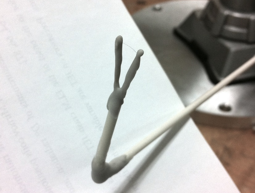
Retarding Potential Analyzer [RPA] A retarding potential analyzer (or RPA, RFEA, gridded energy analyzer) uses a series of grids to selectively collect ions based on their incident energy. A discriminator grid is swept over positive voltages and the current to a slightly negatively biased collector is measured as a function of that voltage. The derivative of this current-voltage characteristic is proportional to the ion energy distribution. Ion beams can be observed directly with this device. We currently use a 12 mm outer diameter RPA with a floating front grid, a discriminator grid and a copper collector:

Double Langmuir Probe: The double Langmuir probe consists of two small sections of tungsten wire that are differentially biased that collect current from the plasma that is a function of the bias voltage. The resulting I-V curve can be used to measure the electron temperature and plasma density.
Single Langmuir Probe: The single Langmuir probe consists of half of the double probe, rf-filtered, which is biased relative to ground and the resulting I-V trace can be used to measured the electron density and the EEDF.
Emissive Probe: A 25 micron thoriated tungsten filament is heated with a floating DC supply and the resulting floating potential of the probe is within a few Te of the plasma potential. This probe is used to measure the variation of the plasma potential in the system, particularly in the region of the ion acceleration.
Magnetic Field Probe: The magnetic field probe is a 5 turn solenoid. Two wires from the solenoid are then formed into a twisted pair which lead to a hybrid combiner to reject common-mode signals resulting from electrostatic pickup. The probe measures the derivative of the magnetic field present within the solenoid. Measurements of the plasma wave amplitude and phase are possible to characterize helicon wave coupling.
Diamagnetic Loop: A simple loop around the chamber can be used to measure the global time-varying magnetic field. This signal is proportional to the component of the electron temperature that is perpendicular to the axially-directed magnetic field lines.
Ion Acceleration
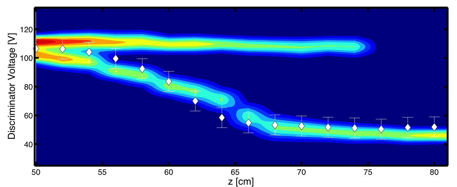
We have observed the formation of an accelerated ion beam population within the plasma near the transition from the Pyrex source to the stainless steel expansion chamber. The ion beam energies exceed 100 eV, which is much larger than the ion sound speed in the system as well as the predicted ion acceleration from simple Boltzmann expansion (which includes the electron density drop). These measurements are highlighted in our recent paper. Below is the z-dependence of the ion energy distribution function for a high-energy beam case (65 eV) measured with the RPA (color - red is highest) as well as the plasma potential measured with the floating emissive probe:
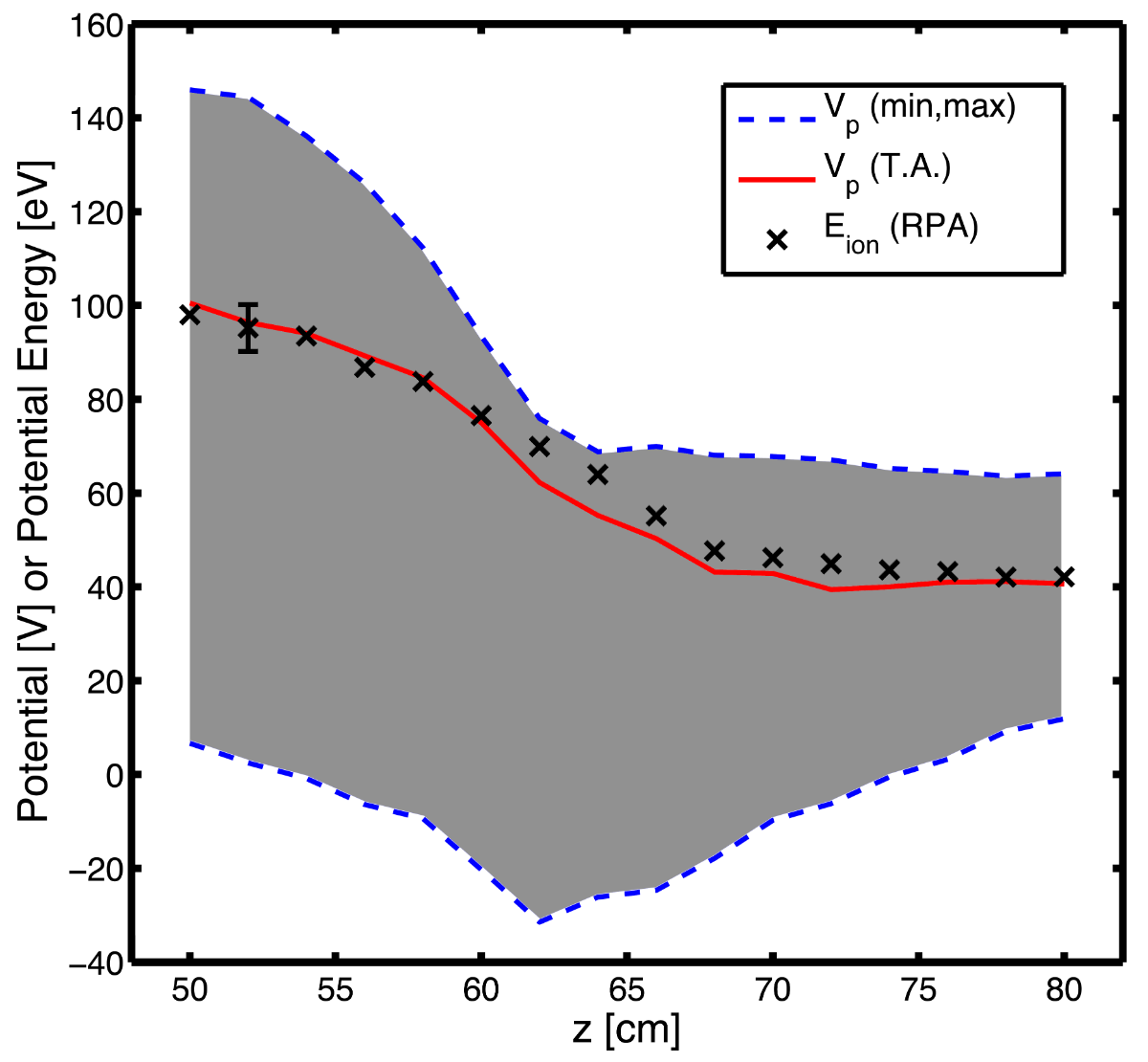
The mechanism behind this ion acceleration is the self-bias effect, detailed in our recent paper. Large, rapid fluctuations of the plasma potential on the RF timescale have been observed with the emissive probe (see below). These fluctuations lead to rapidly forming plasma potential gradients, which the lighter plasma electrons can easily respond to but the massive argon ions cannot. This leads to an initial imbalance in particle flux from the upstream region, and the time-averaged plasma potential in the upstream region rises to compensate. In steady state, a large time-averaged gradient exists which accelerates the ions from the upstream region, as evidenced by emissive probe measurements shown below.

Measurements are underway to investigate the electron energy distribution function's effect on the ion acceleration, as well as further investigation of the use of self-bias as a source of thrust.